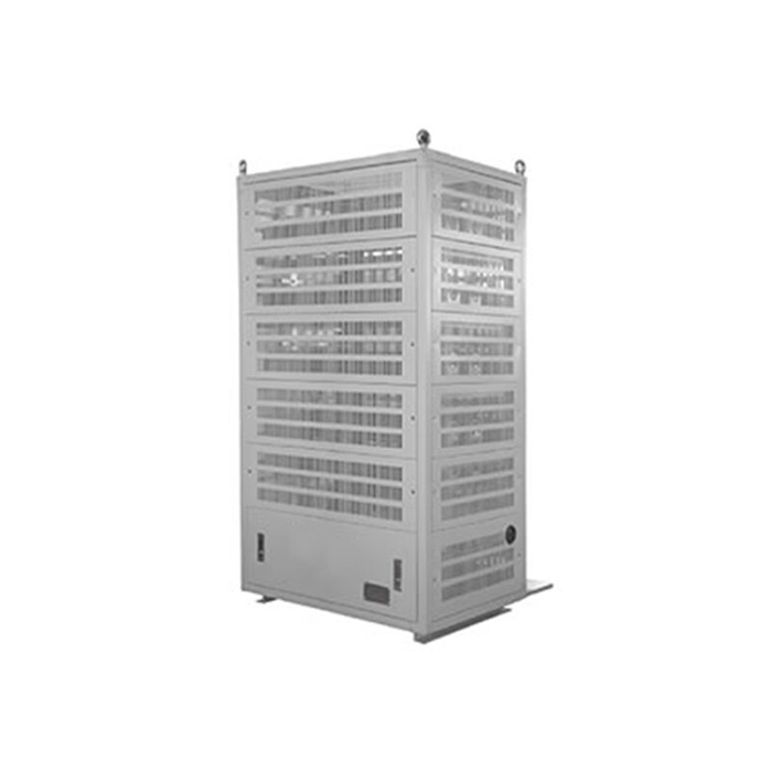
Braking Unit
The function of the braking unit is to divert into a braking resistor the regenerative energy produced in the process of decelerating the motor, converting that energy into heat. Regenerative energy flows from the motor into the inverter DC Bus, manifested as increased bus voltage. The advantage gained using the braking unit is improved braking performance and shorter deceleration time of the load.
PRODUCT DESCRIPTION
Main Features
Product Introduction
The function of the braking unit is to divert into a braking resistor the regenerative energy produced in the process of decelerating the motor, converting that energy into heat. Regenerative energy flows from the motor into the inverter DC Bus, manifested as increased bus voltage. The advantage gained using the braking unit is improved braking performance and shorter deceleration time of the load.
The braking unit in the DBU series is applied to consume in the braking resistor the regenerative energy produced in the deceleration process of the motor in the form of heat energy .In this way ,the braking performance of the frequency inverter is improved and the braking time of the frequency inverter is reduced.
Features
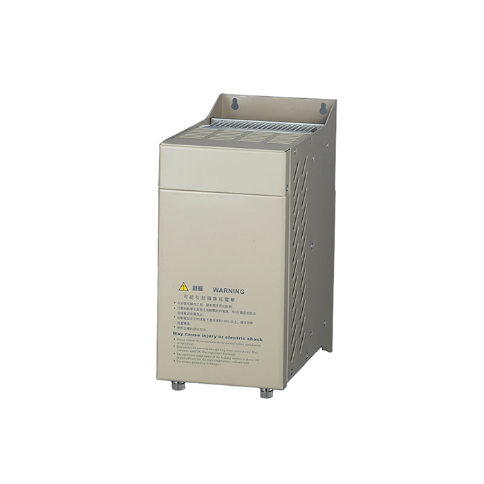
Safety: The tripping function of the equipment against IGBT short circuit and breakdown can effectively avoid the hidden danger of fire caused by the breakdown of IGBT and the overload operation of the resistor in a long time.
Wide Compatibility :The special design of this braking unit allows for the usage of common resistance rather than the non-inductive resistance .It can be adjusted to adapt to 600V-760V DC chopper wave voltage . Further more, this device is used in various type of medium and low voltage frequency inverter (Specially designed product reaches up to 1200V)
Economy: This facility is characterized by high performance cost ratio . With relatively economical price .its quality is same as that of similar imported products. It is therefore considered as the most economical and practical component product for the braking unit of the inverter .
Adaptable to connection in parallel: It adopts a book-shape design can be installed in a parallel connection with zero clearance .It is recommended that up to 3 units can be connected in parallel .
Specification
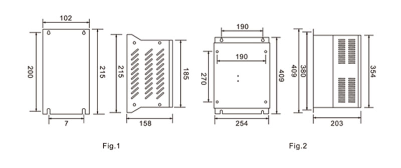
Outline& Mounting Dimension(Unit:mm)
| Type | Mounting Hole Size (mm) | Terminal Screw Size | Wire Size (mm2) |
| 2015/2030/4015/4030/4045 | 6 | M4 | 4-6 |
| 4220 | 8 | M8 | 16-36 |
| Model | Dimensional Drawing | Rated braking current | Max.Braking Current | Chopper Voltage | Mounting Hole Size | Terminal | Weight(kg) | Cable(mm) |
| DBU-2015 | A | 15A | 50A | DC380V±5V | 6 | M4 | 2.3 | 4-6 |
| DBU-2022 | 25A | 75A | DC380V±5V | 6 | M4 | 2.3 | 4-6 | |
| DBU-2030 | 30A | 90A | DC380V±5V | 6 | M4 | 2.3 | 6-8 | |
| DBU-4030 | 15A | 50A | DC630/DC660/DC690V/DC730V±10V | 6 | M4 | 2.3 | 4-6 | |
| DBU-4045 | 25A | 75A | DC630/DC660/DC690V/DC730V±10V | 6 | M4 | 2.3 | 4-6 | |
| DBU-4110 | B | 60A | 200A | DC630/DC660/DC690V/DC730V±10V | 8 | M8 | 13.2 | 16-36 |
| DBU-4220 | 85A | 300A | DC630/DC660/DC690V/DC730V±10V | 8 | M8 | 13.2 | 16-36 | |
| DBU-4300 | 120A | 500A | DC630/DC660/DC690V/DC730V±10V | 8 | M8 | 13.2 | 25-50 | |
| DBU-6220 | 85A | 300A | DC630/DC660/DC690V/DC730V±10V | 8 | M8 | 13.2 | 16-36 |
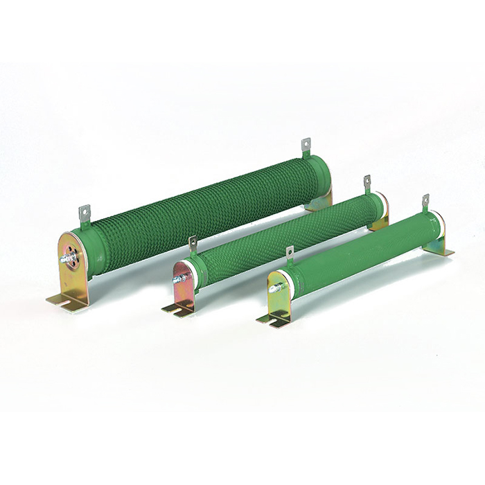
Recommended brake assembly matching specification
| Inverter | Braking Unit | Braking resistor | ||||
| Voltage(V) | Motor(KW) | Model | Qty(PCS) | Recommend resistor value | Resistor specification | Qty(PCS) |
| 220V | 0.75KW | Built-in | 80W200Ω | 80W200Ω | 1 | |
| 1.5KW | Built-in | 200W100Ω | 200W100Ω | 1 | ||
| 2.2KW | Built-in | 300W70Ω | 300W70Ω | 1 | ||
| 3.7KW | Built-in | 400W40Ω | 400W40Ω | 1 | ||
| 380V | 0.75KW | Built-in | 80W750Ω | 80W750Ω | 1 | |
| 1.5KW | Built-in | 200W400Ω | 200W400Ω | 1 | ||
| 2.2KW | Built-in | 300W250Ω | 300W250Ω | 1 | ||
| 3.7KW | Built-in | 400W150Ω | 400W150Ω | 1 | ||
| 5.5KW | Built-in | 600W100Ω | 600W100Ω | 1 | ||
| 7.5KW | Built-in | 800W75Ω | 800W75Ω | 1 | ||
| 11KW | Built-in | 1000W50Ω | 1000W50Ω | 1 | ||
| 15KW | Built-in | 1500W40Ω | 1500W40Ω | 1 | ||
| 18.5KW | Built-in | 1 | 2500W35Ω | 2500W35Ω | 1 | |
| 22KW | Built-in | 1 | 3000W27.2Ω | 1500W54Ω | 1 | |
| 30KW | 4030 | 1 | 5000W19.2Ω | 2500W40Ω | 2 | |
| 37KW | 4045 | 1 | 6000W16Ω | 2000W50Ω | 3 | |
| 45KW | 4045 | 2 | 9600W13.6Ω | 2500W54Ω | 4 | |
| 55KW | 4030 | 2 | 12000W10Ω | 2000W60Ω | 6 | |
| 75KW | 4045 | 2 | 16000W7.5Ω | 2500W60Ω | 8 | |
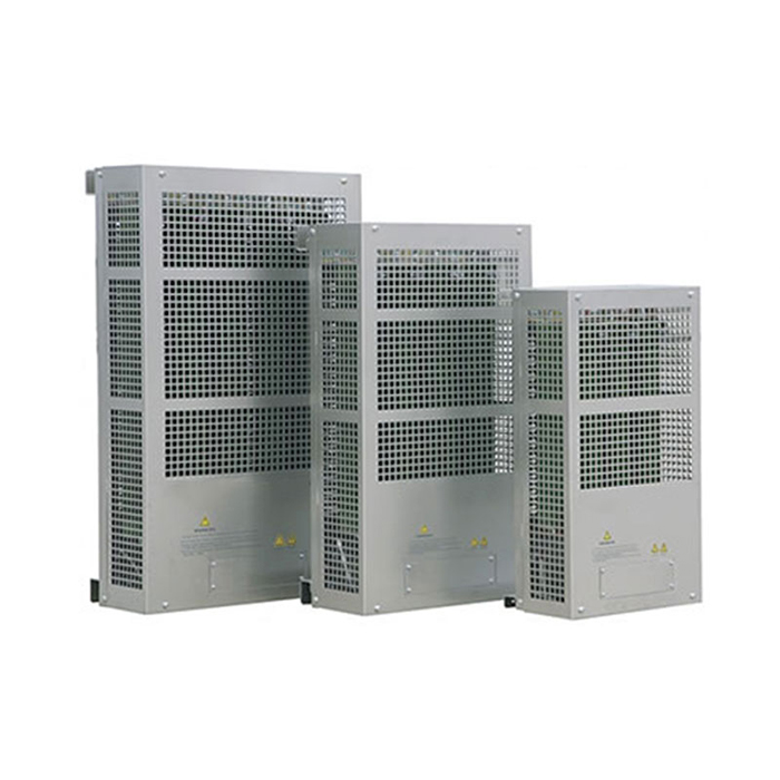
| Braking Resistor Box | Quantity(PCS) | |||||
| 90KW | 4030 | 3 | 9600W20Ω | 3 | ||
| 100KW | 4220 | 1 | 9600W20Ω | 3 | ||
| 132-160KW | 4220 | 1 | 40KW3.4Ω | 1 | ||
| 185-220KW | 4220 | 1 | 60KW3.2Ω | 1 | ||
| 250-315KW | 4220 | 2 | 40KW4.5Ω | 2 | ||
| 315-600KW | 4220 | 3 | 60KW3Ω | 3 | ||
Technical Indications
| Model | AC200V-AC300V | AC380V~AC460V | ||||||
| 2015 | 2022 | 2030 | 4030 | 4045 | 4220 | 4300 | ||
|
Input And Output |
Peak current (A) | 50 | 75 | 90 | 50 | 75 | 300 | 400 |
| Rated Current(A) | 15 | 25 | 30 | 15 | 25 | 85 | 120 | |
| Breaking initial voltage | 380±5V | 630/660/690/730/760V±10V | ||||||
| Maximum Hysteresis Error | About 8V | About 16V | ||||||
| Multiple units | Maximum: breaking unit are parallel connected | |||||||
| Power | DC Bus Voltage Range | DC 243~400V | DC460~800V | |||||
| Indication
Function |
Power ON | The red “power” LED will be on when the inverter DC Bus voltage is above ~35VDC | ||||||
| Braking ON | The green “braking” LED will be on during braking unit work | |||||||
| Ambient | Temperature | -10C~+40C ( -10C~+50C for store) | ||||||
| Humidity | 90% RH (no dew) | |||||||
| Vibration | 1G(10~20HZ), 0.2G ( 20~50HZ) | |||||||
| Protection | IP20 | |||||||
| Structure | Wall mounted | |||||||
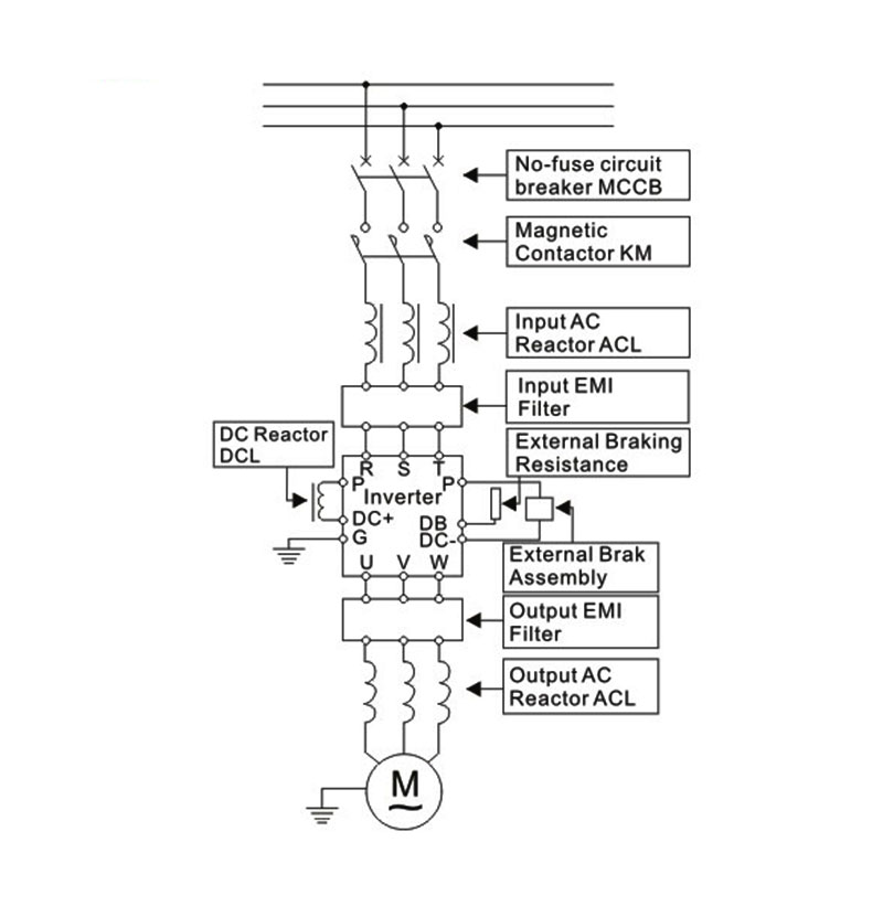
Related drawings
Wiring diagram for inverter system